Reassembly of the Chubb Manifoil Mk4 Combination Lock
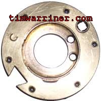
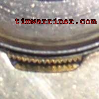
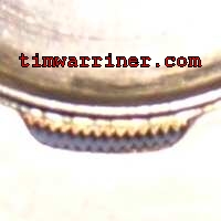
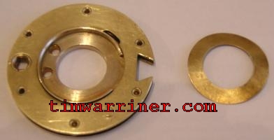
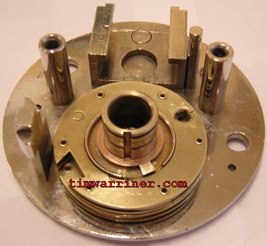
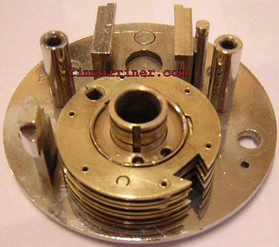
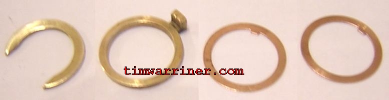
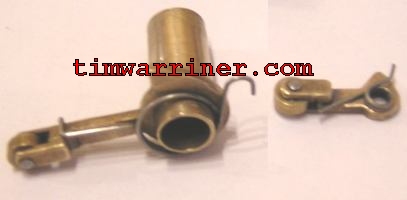
On this page, I explain how to put the Manifoil Mk4 Combination lock back together. It is mostly just a matter of remembering the order of parts. There is nothing difficult here.Before we start, the following three pictures show what a wheel looks like (a) in full view, (b) locked, (c) unlocked and ready for combination changing. An S&G6730 change key has the right dimensions to unlock the wheels, but I haven't tested one to see if it will fit when the back is on the lock.
(b)
(c)
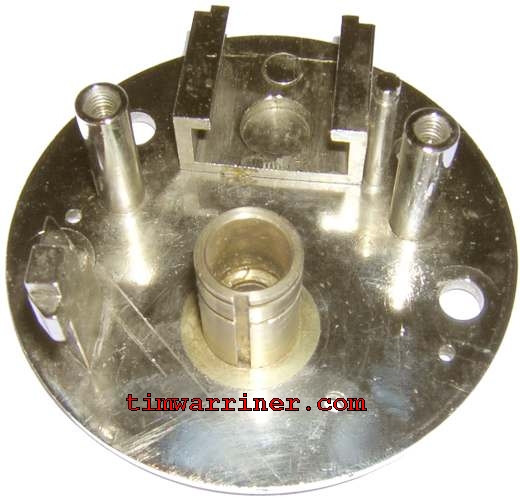
To rebuild the lock from its parts you must start with the base:
The first two parts, in order they will be put down (from right to left). They are the base washer and the first wheel. The wheel goes down with the internal rim part pointing upwards.
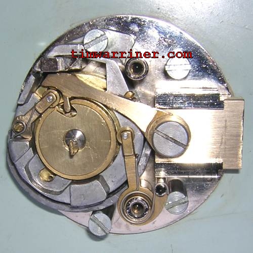
The next three parts to be put down (from right to left): copper washer, fly, copper washer, second wheel:
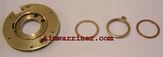
So far (before the second wheel is put down):
The next three parts to be put down (from right to left): copper washer, fly, copper washer, third wheel:
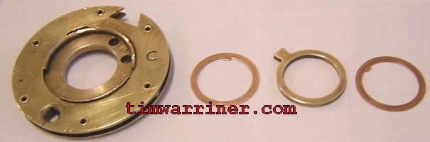
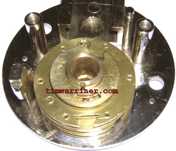
Just before the third wheel is put down:
After the third wheel is put down. If it looks like there are 4 wheels down, it is because of the reflection in the base.
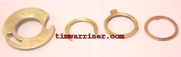
The next four parts to be put down (from right to left): copper washer, fly, clip, first cam. The clip/Circlip just needs a firm push with a screwdriver or similar to slide it into place.
Those parts in place except for the first cam:
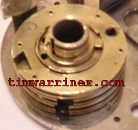
The first cam in position:
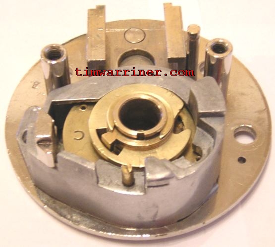
The next picture is the wheel cover in place. It justs slips on if the gates are aligned and pointing away from the bar that the cover fits around. Otherwise it doesn't fit on easily. When the lock is put onto the door, the bolts hold the wheel cover against the base. Until then, it sits loosely over the wheels.
The next four parts to be put down (from right to left): copper washer, copper washer, fly, clip. This fly sits with the protusion pointing downwards.
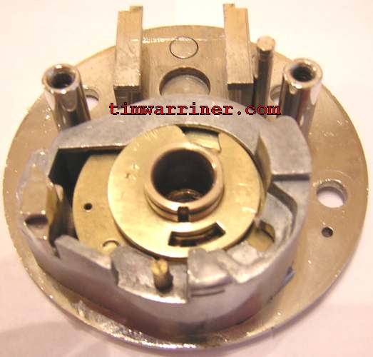
Those parts in place:
The next parts to be put in position are the second cam (not pictured - I forgot...) and the two rollers. The springs on the rollers aren't too strong to be put in place with fingers (and/or a screwdriver), although they may fly off if you aren't careful. They fit as can be seen in the finished lock picture further down.
The next picture shows the remaining parts to complete the lock (before it is fixed to the door). Clockwise from top left there are: the lever (lacking its fence), the lead side-shield (to prevent x-rays from the side of the wheel pack showing where the gates are), the screw-threaded bolt that holds the lever in the lock's (sliding rectangular) bolt, and the (sliding rectangular) bolt itself: (I'm trying to distinguish between the two meanings of bolt)
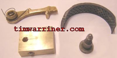
The lead side-shield just slides into position. It may have originally been held in place with double sided tape. For this lock, the lock's cover is the only thing that will keep the side-shield from falling off, but it stays in place ok. To fit the lever, slide the (lock's rectangular sliding) bolt (with the tiny hole on top) into its locked position. Fit the lever into it, with the lever end of the spring in the tiny hole. Put in the screw-threaded bolt to fix the lever in place.
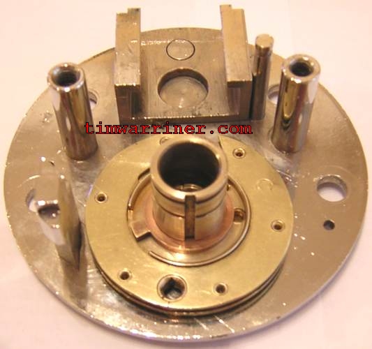
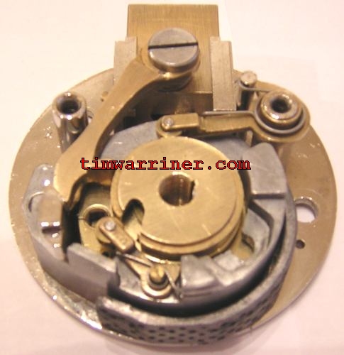
The finished lock:
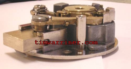
Side view:
Here the lock is shown fitted to the door, with the spline key only inserted half way (so I can take it out easily). Note how the wheelpack cover is now fixed in place with the same bolts that hold the lock to the door. Although the lever is sitting in the drive cam, the gates didn't have to be aligned in this particular case because this lock is missing its fence.
[Go to the disassembly page]
[Go to the main Manifoil page]
[Contact]